
How do you calculate voltage drops in solar power systems? The simplest method to determine the decrease in voltage along the PV wires is to get the cable’s total resistance (Ohms) and multiply it by the current (Amps) passing through the conductor.
The electrical potential drop in any system is primarily caused by the inherent electrical resistance within the conducting material of the cables. In this article, we will focus more on voltage drops in solar PV systems and calculate them in the easiest way possible.
Voltage Drop Calculator For Solar Cables
This calculator will help you determine how much voltage drop the solar PV string will potentially experience. As it connects to other devices such as inverters, charge controllers, or batteries, the PV array will see a decrease in its voltage.
We are concerned about the efficiency of the system and how much electrical potential it may lose. Therefore, this tool will help minimize voltage drop by ensuring you selected the suitable cable sizes.
Using this calculator is pretty simple. Here are the easy steps that you need to follow.
- Select the cable material and the cable size that you want to use. Or, you may enter a specific Ohm/km value if required.
- Enter the distance between the solar panel and other equipment.
- Next, enter the PV string current.
- The next step is to enter the total DC voltage of the PV string.
- Lastly, press the “Calculate” button.
What is Voltage Drop?
Voltage drop pertains to the decrease in a circuit’s voltage level (or electrical potential) due to impedance (resistance and reactance) as the electricity flows through a conductor or a metallic cable.
It pertains to the difference between the electrical potentials of the starting and the end points of an electrical cable. Voltage drops as the internal resistance of the wire or conductor increases.
Since the amount of current flowing through the conductors turns into heat due to the electrical resistance, the voltage decreases at the receiving end.
Voltage Drop Formula for Solar PV Cables
The voltage drop is directly proportional to the current flowing through the cable, its resistance value, and the length of the cable itself. Here is the formula that you can use to determine the decrease in electrical potential for solar PV cables.
Vd = 2 x L x I x R / 1000
Where:
Vd = Voltage Drop (Volts)
2 = accounts for the total length of positive and negative DC cables (unitless) by doubling the one-way circuit length
L = one-way circuit length (meters)
I = full load current or the module’s Isc x number of strings (Amps)
R = resistance per kilometer, refer to the cable’s datasheet (Ohms/kilometer)
1000 = converting meters to kilometers (m/km)
V = PV Array Voltage
Also, you may want to check out the solar panel efficiency calculator in our previous article.
Voltage Drop: What the NEC Handbook says about it
The NEC is a good place to start for manual voltage-drop calculations. Table 8 in Chapter 9 contains DC resistance values per 1,000 feet. The reactance and ac resistance per 1,000 feet are shown in Table 9 of Chapter 9. The NEC Handbook follows the Tables with some voltage-drop equations and example calculations.
To be clear, the NEC does not specify a voltage drop. In contrast, fine print notes (FPN) in Articles 210 and 215 on branch circuits and feeders suggest that “reasonable efficiency of operation” occurs if voltage drop is limited to less than 3% on feeders and branch circuits, and less than 5% overall (210.19(A) FPN No. 4 and 215.2(A)(3) FPN No. 2.) These FPNs are not legally binding and were not designed with PV in mind.
Nonetheless, they serve as helpful reference points. The Code does make one general requirement in Article 250.122(B): if the current-carrying conductors are upsized for voltage drop, the equipment grounding conductor (EGC) must also be proportionally upsized. Article 690.45(A) of the 2008 NEC includes an exception to this rule, stating that it is not necessary to upsize the dc EGC in a PV system to address voltage drop. As a result, in PV source and output circuits, the EGC is generally sized in accordance with Table 250.122.
What is the best source for good voltage drop calculations?
Another option for performing voltage-drop calculations is to use one of the many electrical calculator programs that are available. Some programs can be accessed online, while others must be downloaded to your computer. There are also handheld calculators with special buttons for electrical functions. The majority of these calculators are reasonably accurate and useful in typical situations.
Most, however, will not show you exactly how the calculations are performed so that you can verify the answer. Most will struggle to adapt to nonstandard applications such as PV. Many, for example, only allow dc voltages of up to 48 V, and only a few allow temperature or power factor adjustment.
The best source for accurate voltage drop calculations for your project is a licensed electrical engineer who is familiar with both PV and voltage drop issues.
Another Good Electricity and Water Analogy Yet Again!
The best analogy for this is a water hose system. You may imagine the water faucet as the power source, water flow as current, water pressure as the voltage, and the small holes along the hose length as resistance.
The greater the number of holes, the less water flows at the end of the hose. It also causes a decrease in the water pressure at the end of the water hose.
So, the difference between the water pressures at both ends of the hose represents the voltage drop. The amount of water that has escaped through the holes will be considered the electricity losses.
Two Ways to Determine Solar Cable Resistance
There are a lot of ways to determine the total resistance of a solar PV cable. The easiest way is to find the cable datasheet, which will tell you its typical resistance per kilometer value (Ohms/kilometer). Multiplying it with the length of the 2-way circuit length of the conductor, you can get the resistance of the whole cable.
Another way is to use an Ohmmeter. An Ohmmeter is a device that can measure the electrical resistance of almost any type of material. You can typically find it as one of the features of a multimeter. Using this method is probably the most accurate way of getting the cable’s resistance value.
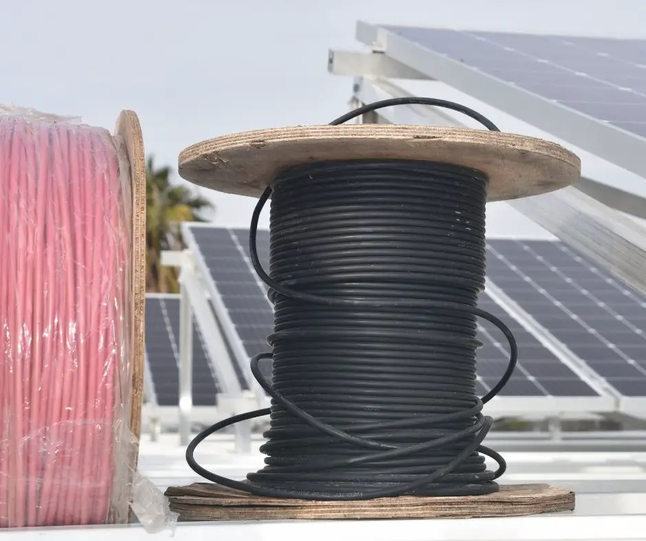
What are the commonly used sizes of cables for PV system applications?
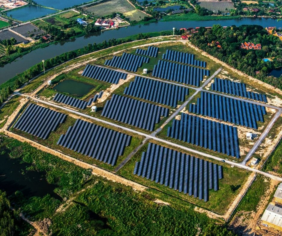
A considerable part of the materials to build a PV system is the DC cabling. Just try to imagine a solar farm with multiple PV arrays and PV strings. There will be a need for many reels of solar cables to connect the PV modules to other equipment. But, what sizes are commonly used for solar power plants?
Here are some of the commonly used sizes of solar PV cables in solar panel systems.
- 4 sq. mm.
- 6 sq. mm.
- 10 sq. mm.
- 16 sq. mm.
- 25 sq. mm.
- 35 sq. mm.
- 50 sq. mm.
- 70 sq. mm.
Table of Solar PV Cable Sizes
| Ref. No. | Cable Size | Copper Cable Conductor resistance [Ω/km] at 20°C | Aluminum Copper Cable Conductor resistance [Ω/km] at 20°C |
| 1 | 4 sq. mm. | 5.0900 | 7.4100 |
| 2 | 6 sq. mm. | 3.3900 | 4.6100 |
| 3 | 10 sq. mm. | 1.9500 | 3.0800 |
| 4 | 16 sq. mm. | 1.2400 | 1.9100 |
| 5 | 25 sq. mm. | 0.7950 | 1.2000 |
| 6 | 35 sq. mm. | 0.5650 | 0.8680 |
| 7 | 50 sq. mm. | 0.3930 | 0.6410 |
| 8 | 70 sq. mm. | 0.2770 | 0.4430 |
| 9 | 95 sq. mm. | 0.2100 | 0.3200 |
| 10 | 120 sq. mm. | 0.1640 | 0.2530 |
| 11 | 150 sq. mm. | 0.1320 | 0.2060 |
| 12 | 185 sq. mm. | 0.1080 | 0.1640 |
| 13 | 240 sq. mm. | 0.0820 | 0.1250 |
How much voltage drop is acceptable in a solar PV plant?
Following IEC 60364-7-712, “the voltage drop from the most remote module in the array to the input terminals of the application circuit should not exceed 3 % of the PV array voltage at its maximum power point.” This citation can be found on page 22 of the publication.
If you want a copy of the IEC 60364-7-712 document, you may join our email list and contact us through our Facebook page for verification.
For example, if your solar PV array voltage is 900Vdc, the electric potential at the other end of the solar cable should be greater than 873Vdc. It means the allowable voltage drop should not exceed 27Vdc, which is 3% of 900Vdc.
What causes voltage drop in a PV system?
Many factors may affect the voltage drop of the cables in a PV system. As discussed earlier, the main culprit is the resistance of the conducting body. But, if we look at it, we will find out other things that might also contribute to the decrease of the circuit’s voltage at the receiving end. Here are some of them listed below.
- Cable Resistance Factor
- Cable Length
- Temperature
- Current Source
- Voltage Source
- Cabling Workmanship
Why is voltage drop calculation significant?
Calculating the voltage drop of an electrical connection is crucial to the system’s safety and performance. Without doing voltage drop calculations, you might install the wrong size of cables for the particular application.
For example, installing a smaller cable might overload the circuit when you don’t do the proper calculations. The overloading of a solar PV cable poses a considerable risk of overheating, fires, or even electrocution.
Another aspect is the economic part of it. When you don’t know what size you need to install, you might buy an oversized cable and lose a significant amount of money.
Thus, doing a proper voltage drop calculation will protect not only your pocket but also the safety and integrity of your solar panel system.
Principles for Minimizing Voltage Drop
Keeping all other factors constant, designing with the following principles in mind will help minimize voltage drop:
- Higher voltage transmission results in lower losses. In fact, doubling the voltage reduces the voltage drop by a factor of four for the same power.
- Voltage drops will be smaller over shorter distances.
- Three-phase transmission is more efficient than single-phase transmission.
- The use of larger conductors results in a lower voltage drop.
- Copper conductors with the same size will have lower voltage drops than aluminum conductors.
- Transmission with two dc conductors will result in lower losses than transmission with two ac conductors, especially with relatively large conductor sizes like 350-kcmil and larger. This effect, however, is much smaller for inverter output circuits.
- For large alternating current circuits, use parallel conductors.
- Lowering the temperature of the conductors will reduce voltage drop.
- The higher the power factors, the better.
- Take note of the type of conduit used. The type of conduit makes almost no difference in the voltage drop for ac circuits with small conductor sizes (less than 3/0) and power factors of 0.85 to 1.0; for a power factor of 0.85 and larger wire sizes (3/0 and above), PVC is best, but aluminum is better than steel. PVC is still the best choice for PV inverter-output circuits with a power factor close to 1.0 and larger wire sizes, but steel outperforms aluminum.
Conclusion: Solar PV Cable Voltage Drop Calculation
No one should ever underestimate the importance of voltage drop calculations for any system. We will never know how much time, money, and resource we will save by knowing the correct cable size through this simple computation.
You may choose to memorize the voltage drop formula and the cable specifications or bookmark this page for future use.
Doing the right thing will give you peace of mind by the end of the day. And, that includes being extra careful with cable sizing and the system design of your solar power plant. It will add more to the reasons why we should use solar energy.
If you want to learn more about solar power and other renewable energy sources, sign up to our email list now and be part of the Solar Powered Fam!


