When you want to be as accurate as possible with your design, you will need the help of tools like CAD (computer-aided design) software. Now, if you already have the CAD drawings, you might want to import them into the HelioScope’s design environment to increase the PV design accuracy. But, how will you do it?
In this tutorial, I will walk you through on how to use your CAD drawings in the solar PV design software. It might require a little knowledge about the AutoCAD software and basic image editing.
Here are the five simple steps on how to “import” your CAD drawing into HelioScope properly.
- Prepare Your CAD Drawing
- Convert CAD File To A JPG Image
- Start Creating The HelioScope Project Design
- Import The Drawing Into The PV Design Software
- Scale Your Drawing Inside HelioScope
Step 1. Prepare Your CAD Drawing
This step will make sure that your drawing is ready to be used as a reference object inside the HelioScope application. If CAD is not your cup of tea, you may want to find someone familiar with the appropriate software to edit this file. Examples of this tool include AutoCAD, TinkerCAD, FreeCAD, and others.
Here are some essential points that you need to follow to obtain a proper design for your system.
- North-Orientation of the Drawing.
- Dimensions.
- Object labeling.
Displaying the North Orientation of the Drawing
As a common practice, designers and drafters may include the north arrow orientation in their drawings. This will let you know where the building is located in relation to the surroundings.
But usually, it may not always be upright, especially when the main object or building is not perfectly oriented towards the North.
When you have the CAD file of the building, you need to make sure that the drawing is oriented towards the North and the North arrow points upward.
To do this, here are some few steps you can follow using AutoCAD.
- First, create a vertical straight line beside the drawing, long enough that you can see it easily.
- Select all objects in the drawing by pressing “CTRL+A”.
- Type “AL” to call out the “Align” function and hit the “Enter” key.
- Locate the North arrow in the drawing.
- Click the tip of the North arrow and then click the top of vertical straight line.
- Click the opposite point of the North arrow tip and then click the bottom point of the same vertical line.
- Hit the “Enter” key twice.
- You may delete the vertical line now if you like.
Why is it necessary, though? It will help in making this task a lot easier. Since we will use the HelioScope mapping system, it is best to prepare our drawings to save time. It is also a lot easier and more accurate to do this in CAD software.
In short, always make your drawings to orient Northward.
Drawing Dimensions Must Be Shown
Displaying precise dimensions of your drawing will help you a lot in designing with HelioScope. It makes scaling of the design inside the program more straightforward and quicker.
It means you have to add clear dimensioning details for at least a single straight line.
For example, you can create or draw a line or, let’s say, 50 meters in length just above the building drawing and indicate its dimensions for clarity.
- In AutoCAD, this can be done by typing “L” and hitting enter.
- Then, click at your desired starting point. After that, make sure you turn the “ORTHO” mode on by pressing “F8” for straight-line restrictions.
- Next, move the mouse cursor slightly to the right-hand side, enter 50 (if it is scaled 1:1 m) or 50000 (if scaled 1000:1 m); the length may vary as long as the line will be easily visible.
- Hit enter twice.
- Then, type “DLI,” hit enter, and click on the endpoints of the line. After that, drag the mouse a little bit upwards and hit the left mouse button.
We will use the dimensions displayed on the drawings to match the distances inside the HelioScope mapping environment. It allows for more accurate measurement of the building and estimation of the number of solar modules you can install within its limits.
You see, when the drawing is not accurate, it will impact the credibility of the system design when it comes to the installation stage. When you overestimate the amount of space on your plan, you might end up not fitting all the solar panels on the roof or building. On the other hand, you might waste the available space and not maximize the solar panel system.
Step 2. Convert CAD File To A JPG Or PNG Image
So, after orienting your drawing towards the North and displaying a precise dimension detail, it is now time to go to the next step. You will then need to convert the CAD file into JPG or PNG format.
Although there is no such thing as “Save as JPG” in the CAD software, there are still many ways to convert it to a JPG file. How can this be done? There are so many ways to do this step. But here are my favorites.
By Printing the Drawing as JPG or PNG Image
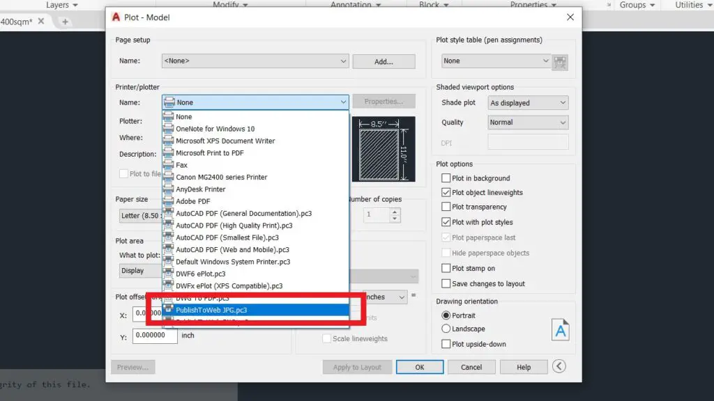
A very straightforward built-in function within the CAD software is printing your drawings and exporting them as JPG files. All you need to do is press CTRL+P and choose the printer/plotter with the “PublishToWeb JPG.pc3”. Then, select the option for “Default paper size…”.
After that, click onto the Plot area’s “What to plot” and choose Window. Click on the drawing in such a way that the building is enclosed within your rectangular window selection. This is done by clicking on the two opposite corners surrounding the building drawing.
Hit the “OK” button and save the file into your desired folder. That’s it; you have converted your CAD drawing into a JPG file.
By Using the Snipping Tool
The snipping tool is my favorite and easiest way to convert the CAD File to JPEG format.
You can do the same steps as the “Print as JPEG” option for this to work correctly, but don’t hit the OK button.
You need to click on the preview button instead, and from there, you can open the snipping tool. Use the tool to snip the drawing from your screen and save it as a JPG file.
By Using the Print-Screen Key and Paint
Among many other techniques, this one is classic!
For this method, you can also follow the “Print as JPEG” option, but instead of the snipping tool, press the print screen button (PRTSC) on your keyboard and open the Paint program. Paste the screenshot by pressing CTRL+V and save the file in JPG or PNG format.
There are at least a dozen of ways to do this step. So, it’s up to you which one you choose to do where you are comfortable.
Step 3. Start Creating the HelioScope Project Design

This step can be intimidating for many, but you will realize this is pretty simple with the proper guidance and consistent practice. You can read and follow my step-by-step HelioScope guide to quickly get started on this.
It is just a matter of logging in to your account or signing up for a free account. Then the next moves are creating a brand new project, entering few project details, and just like that, you have already started the project design creation.
Once you have set this up, you will be ready for the next steps.
Step 4. Import The Drawing Into The PV Design Software
Importing your design into the HelioScope environment is an easy task.
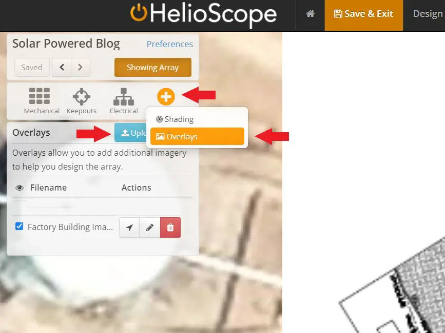
After logging in and creating the new project, you will see the tools inside the design environment. In the upper left corner, you will see the “Advanced” tool. By clicking it once, you will see a submenu “Overlays,” and you have to click on it.
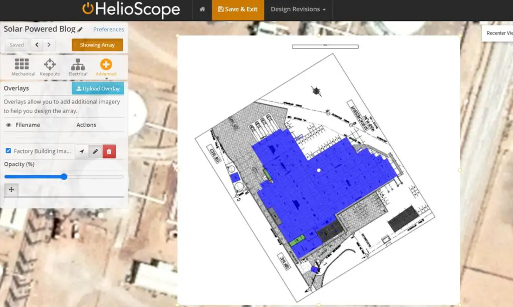
After that, you will see the “Upload Overlay” button. Click on it and locate the JPG format of your drawing from your folder and upload it into the HelioScope system by double-clicking the file.
Now, you have just successfully imported the drawing into the design environment. However, we won’t stop there yet. Let’s continue to the next step.
Step 5. Scale Your Drawing Inside HelioScope
The next step is to have the proper scale of your drawing inside the HelioScope design system. In this part, you will see why you have to do the preparations from the previous steps.
Creating a Distance Reference Object Inside HelioScope
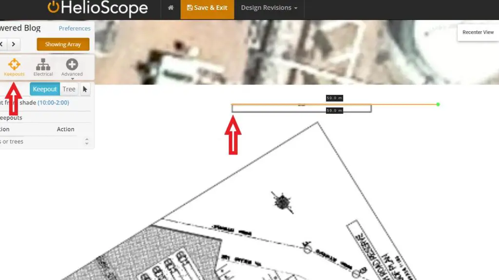
For the reference line, you need to create an object with a dimension on it. You can choose to use either a modules field segment under the “Mechanical” menu or a “Keep out” object under the keep out menu.
Create a horizontal straight line by holding the “Shift” button while making the object. Make sure it matches the dimension that you indicated on the drawings.
Adjusting the Uploaded Overlay Image
Now, it is time to start scaling the CAD drawing image inside the design environment.
Click on the “Advanced” menu and choose “Overlays” mode. You will then see under the “Filename” section the image file that you have uploaded. Notice the little pencil icon on its right side and click it. This will make the overlay image adjustable in size.
Notice that you can edit the picture using the small circular objects or white dots located in the center, corners, sides, and just outside the image box. Here’s what each of them does.
- Corner dots – allow you to expand or shrink the overlay image while maintaining its aspect ratio.
- Side dots – stretches the overlay image towards the desired direction.
- Center dot – allows you to move the overlay object.
- Outside dot – rotates the picture either clockwise or counterclockwise with reference to the center dot.
Warning: Avoid using any of the side dots because it might mess up the scale factor of your drawing.
The outside dot can also control the orientation of the drawing. We don’t need to use it here since we have already set our picture to be oriented towards the North from step 1.
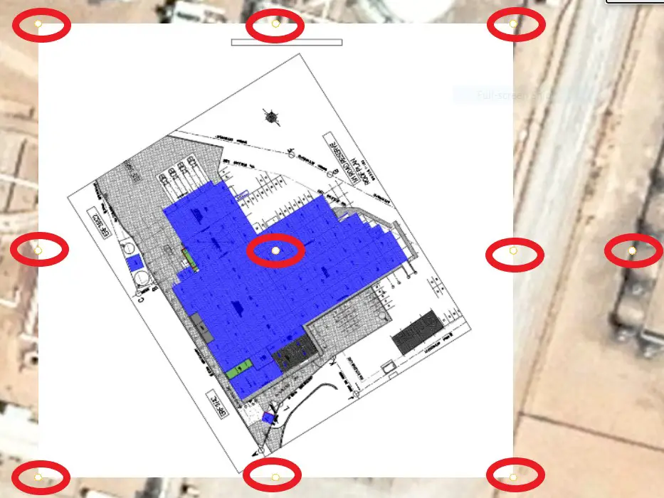
You will only need to adjust any of the corner circular white dots. This will increase or decrease the scale of the object based on which direction you move it into.
Align the object for distance referencing to your drawing and adjust the overlay image to match it. By doing this, you will eventually have your CAD drawings inside the HelioScope environment in proper scale. You can now create a solar PV system design with higher accuracy and precision.
When Will You Need To Import CAD Into HelioScope?
So, when will you be needing to use CAD drawings when designing with HelioScope?
It’s when there’s a new building that you want to make a design from.
Or when HelioScope’s built-in maps are not yet updated on the area where the building is. When you want to be as accurate as possible in your solar PV design, you will want to use the CAD drawings in the solar design software.
Final Thoughts
Preparing the designs for on-grid solar systems can be pretty straightforward. It is especially true when you could plot the solar panels on its integrated mapping system. However, the most common problem that solar designers face is when the building or property is not yet reflected anywhere on the map within the software.
Integrating CAD drawings into any solar PV software can be confusing sometimes, especially if you don’t know where to start. In this tutorial, you will be able to design any PV projects whether it’s on the map or not.
It’s because you can now import your CAD drawings (in image format) inside the HelioScope environment and scale it properly for a more accurate solar panel design. You might need to practice it a few more times to be more confident in doing it with your following plans.
Sign up for our email list now and be part of the Solar Powered Fam!


")